Load window
Provide minimum and maximum LED forward voltage, required output current, maximum load power and expected tolerance. The proposed operating point must stay inside the published regulation window across the intended temperature range.
Driver integration workflow
A driver review starts with the LED module, not a nominal wattage. The workflow records forward-voltage range, target current, mains conditions, enclosure temperature and the required control behavior before a model reaches fixture validation.
Provide minimum and maximum LED forward voltage, required output current, maximum load power and expected tolerance. The proposed operating point must stay inside the published regulation window across the intended temperature range.
State input voltage, luminaire enclosure, ambient range, thermal interface, IP need, surge environment and access for replacement. A component rating cannot be extended to the finished luminaire without system validation.
Name DALI-2, 0-10V, phase-cut, PWM or standalone operation. Include dim-to-off, emergency response, sensor zoning, auxiliary power and the commissioning party who owns the final sequence.
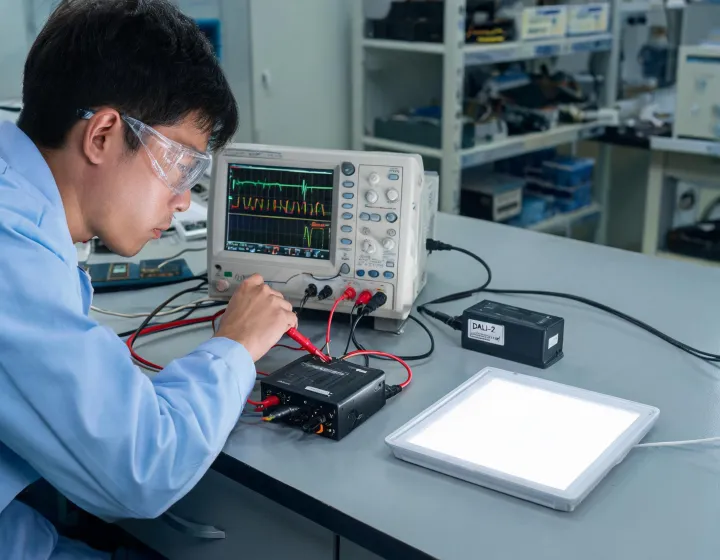
A useful package identifies the tested LED module, driver suffix, firmware or configuration where relevant, input condition, enclosure temperature and control device. These details make a bench result repeatable.
Power factor and total harmonic distortion should be reviewed at the operating load, not assumed from a family maximum. Surge protection is one layer in a coordinated site strategy. Dimming performance depends on the complete circuit and controller. UL, CE and RoHS references must match the selected product and destination; they do not certify the completed luminaire by association.
Photometric output still belongs to the complete light engine, optic and thermal system. A current change can alter luminous flux, efficacy, color stability and lifetime. Fixture manufacturers remain responsible for system-level safety, EMC, thermal and performance validation.
Send the LED load window, enclosure condition and control interface. Open decisions will remain visible in the response.